Domestic ventilation systems performance
Contents |
[edit] Introduction
The Building Regulations Part F 2010 introduced the requirement for testing fixed ventilation systems (Regulation 42, 2010). Following on from the inclusion of airtightness testing in Part L1 2006 significant improvements in as-built measured air tightness were observed. Lower airtightness levels result in less natural infiltration and the importance of ‘Build Tight, Ventilate Right’ becomes increasingly significant.
Part F sets out minimum ventilation rates for dwellings ventilated by intermittent extracts (System 1), continuous extract, including centralised and decentralised (system 3) and whole house ventilation (system 4). In the case of centralised system 3 and system 4, these historically have been commissioned to ensure the correct airflow rates are measured at each terminal. The installed performance of system 1 and system 3 (decentralised) types has historically (pre 2010) not been measured but now must be tested.
Following the implementation of the 2010 Building Regulations and publication of guidance in Approved Document F, BSRIA has observed that more than 90% of system 1 and system 3 (de-centralised) installations failed to meet minimum requirements. As a consequence of failures it has been observed that higher rated fans have been selected that will move more air, but these use more energy than is needed, and create more noise (and are therefore more likely to be switched off and left off).
These results raised questions as to whether the manufacturers’ stated performance values for their fans were correct, whether measurement methods employed were accurate, whether fans were being used in unsuitable applications or whether low observed airflow rates were purely a result of poor installation. As a result of potential measurement method inaccuracies an amnesty was implemented and testing was not required.
BSRIA undertook a number of studies to ascertain the cause of inaccuracies and alleged poor performance.
[edit] Product performance
Leading manufacturers of intermittent operating extract fans supplied BSRIA with the most widely used fans for performance testing. The vast majority of branded fans achieved the manufacturers’ rated specification when tested in the laboratory in accordance with the appropriate standard.
[edit] Measurement methodology
The Domestic Ventilation Compliance Guide, a supporting document to Part F, shows a vane anemometer and hood assembly as a type of equipment that could be used to demonstrate compliance. It was found in BSRIA’s tests that this type of equipment (being the most widely utilised test equipment) actually creates a resistance which then affects fan performance in exactly the same way as if you were to partially block the inlet or outlet of the fan. The degree of change in performance is dependent on the type, make and model of fan and the volume of air moving through the fan. The higher the flow rate, the more the fan performance is adversely affected. This means that a perfectly installed system in a well-designed application could still be seen to be apparently underperforming when it is actually fully compliant.
BSRIA found that the potential error could be in excess of 40% for 60l/s applications and 20% for 15l/s and 30l/s installations. The result of these findings meant that more acceptable measurement methods needed to be developed.
After much consultation the agreed solution was to deem three measurement methods acceptable:
[edit] Unconditional method
This method covers measurement equipment that does not apply a resistance to the system, or automatically compensates for it, and therefore the reading displayed can be assumed to reflect the true performance of the installation.
[edit] Conditional method
This method relies on having specific correction factors for both the fan and the measurement equipment combination. For every type, make and model of fan in combination with every variation of hooded anemometer used, there is a unique correction factor. Only when the correction factors are used can the reading obtained be assumed to reflect the true performance of the installation.
[edit] Minimum benchmark method
This method uses the typical errors observed to set benchmark levels which factor in the generic impact of hooded vane anemometer test equipment. This is a crude approximation and can lead to errors.
This method does not guarantee compliance. As a consequence of using these benchmarks, compliant systems will be deemed non-compliant and non-compliant systems will be deemed compliant.
It should be noted that it is a requirement for all test equipment to be UKAS calibrated on an annual basis. Calibrations should be for the system (the instrument and the hood assembly used) and must be for volumetric flow not air velocity. As standard, instruments are provided with calibrations for velocity only and only generic coefficients are provided for the accompanying hood. Failure to have and use the correct calibration coefficients will result generally in measurement inaccuracies.
[edit] Application
A number of installations use fans in unsuitable applications. This is as a result of both poor design, but also installers deviating from the design, for example, changing the duct materials, increasing run lengths or using inappropriate terminals. These unsuitable applications usually increase the system resistance and therefore affect fan performance.
[edit] Installation
The widespread use of flexible ducting, and its poor installation, results in squashed or restricted ducts, connections to fan spigots or exhaust terminals where the duct is required to turn through 90°, or have a bend where the radius is less than the diameter of the ducting, again applying additional resistance.
In-situ measurements demonstrating non-compliance may not be as a result of a single failure, but a combination of issues. To ensure compliance, numerous factors need to be taken into consideration and will require checks at design, installation and verification stages.
[edit] Design
- Does the design limit system resistance?
- Have the lengths of ducts been kept to a minimum (Flexible ducting maximum lengths, are 1.5m for axial fans and 6.0m for centrifugal fans)?
- Have the number of bends been kept to the minimum?
- Has the right terminal been selected?
- Considering the manufacturers’ fan performance data, does the selected fan have the capacity to work in the designed installation?
- Can the design be implemented or does placement of other services or structural elements obstruct duct routes?
- Does the design take into consideration the design air permeability of the dwelling?
- Have ducts outside the thermal envelope been specified to be insulated?
- Have vertical ducts been designed to incorporate a condensate trap?
- Has adequate air transfer (door under-cuts) been allowed for?
[edit] Installation
- Has the design been followed?
- Does the installation limit uncalculated losses?
- Has flexible ducting been installed such that it is extended to 90% of its total length?
- Do flexible bends have a radius at least equal to the diameter of the duct?
- Is ducting supported to prevent sagging?
- Have any seals around ducting penetrating the structure been sealed in such a way as to restrict the ducting?
- Are horizontal penetrations through the building envelope angled downward to prevent water ingress?
[edit] Verification
- Are high noise levels noticed at either start-up or during operation?
- Are the controls compliant with requirements (15 minute over-runs for intermittent fans in rooms without opening windows or operated by the light switch for rooms with no natural light, and manual controls clearly identified)?
- Has the test equipment used for verification been UKAS calibrated within the last year?
- Have the correct calibration coefficients been used for the measurements?
- Have test results been provided to building control within 7 days of the test?
[edit] Conclusion
The amnesty for testing ended on the 1st January 2014, and future compliance can only be achieved by good design, installation and commissioning with accurate measurements. Engaging designers, installers and testers who understand the importance of each stage of the process will be key to delivering compliant systems.
If any of the following three key points is not met, the installation is likely to be non-compliant and warrants further checks:
- On first fix inspection, does the ducting look professionally installed? No sharp bends, no excessive use for flexible ducting and no sagging where it is used.
- Does the actual installation mimic the design information? Does it follow the ductwork routes on the design drawings; is the use of rigid ducting as indicated in the drawings; are the terminal grills etc. as specified in the design?
At final inspection, with system in operation, do the controls work, are they correctly labelled and does it sound noisy?
This article originally appeared in the September 2014 edition of BSRIA’s Delta T magazine. It was written by Chris Knights, Business Manager, BSRIA Compliance. It has been posted here by --BSRIA 09:41, 9 December 2014 (UTC)
[edit] Related articles on Designing Buildings Wiki
- Air conditioning.
- Air infiltration testing.
- BSRIA publishes new edition of BG29.
- Changes to Building Regulations Part F.
- Closing the gap between design and as-built performance.
- Condensation.
- Cross ventilation.
- Displacement ventilation.
- Heat recovery ventilation.
- HVAC.
- HVAC and smart energy post-Brexit.
- Locating ventilation inlets to reduce ingress of external pollutants into buildings: A new methodology IP 9 14.
- Mechanical ventilation.
- Natural ventilation.
- Passive building design.
- Performance gap.
- Thermal comfort.
- The history of non-domestic air tightness testing.
- Ventilation.
Featured articles and news
ECA progress on Welsh Recharging Electrical Skills Charter
Working hard to make progress on the ‘asks’ of the Recharging Electrical Skills Charter at the Senedd in Wales.
A brief history from 1890s to 2020s.
CIOB and CORBON combine forces
To elevate professional standards in Nigeria’s construction industry.
Amendment to the GB Energy Bill welcomed by ECA
Move prevents nationally-owned energy company from investing in solar panels produced by modern slavery.
Gregor Harvie argues that AI is state-sanctioned theft of IP.
Heat pumps, vehicle chargers and heating appliances must be sold with smart functionality.
Experimental AI housing target help for councils
Experimental AI could help councils meet housing targets by digitising records.
New-style degrees set for reformed ARB accreditation
Following the ARB Tomorrow's Architects competency outcomes for Architects.
BSRIA Occupant Wellbeing survey BOW
Occupant satisfaction and wellbeing tool inc. physical environment, indoor facilities, functionality and accessibility.
Preserving, waterproofing and decorating buildings.
Many resources for visitors aswell as new features for members.
Using technology to empower communities
The Community data platform; capturing the DNA of a place and fostering participation, for better design.
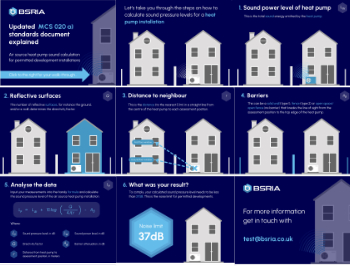
Heat pump and wind turbine sound calculations for PDRs
MCS publish updated sound calculation standards for permitted development installations.
Homes England creates largest housing-led site in the North
Successful, 34 hectare land acquisition with the residential allocation now completed.
Scottish apprenticeship training proposals
General support although better accountability and transparency is sought.
The history of building regulations
A story of belated action in response to crisis.
Moisture, fire safety and emerging trends in living walls
How wet is your wall?
Current policy explained and newly published consultation by the UK and Welsh Governments.
British architecture 1919–39. Book review.
Conservation of listed prefabs in Moseley.
Energy industry calls for urgent reform.


